

Cable Logging Operations
Description
Cable yarding consists of a system that uses cables to transport material from the woods to the landing. Material may be fully or partially suspended for all or a portion of the yarding distance. The cables are strung in corridors through the stand. No yarding equipment other than the cables and a carriage are operated within the stand itself. There are number of different rigging configurations that can be used in cable logging.
Rigging Configurations
There are many different rigging configurations, but they are typically broken down into four distinct types, highlead, standing, running, and live. The highlead system is not a skyline system. The standing, running, and live systems are skyline systems, meaning that they all have a skyline cable.
Standing Skyline
There are many different ways to rig a standing skyline. The main feature of a standing configuration is the fact that the skyline remains fixed, its length does not change during operation. The type of carriage used and whether a haulback is required determines the number of lines used in a standing skyline. It is capable of operating with a manual, mechanical or motorized slack pulling carriage. Without special rigging, this system is not capable of using a non slackpulling carriage.

Figure 1. - Standing Skyline Configuration.
When operating with a manual or motorized slackpulling carriage, this system requires a two-drum yarder. It will have a skyline and a mainline. When operating with a mechanical slackpulling carriage, this system requires a three-drum yarder. It will have a skyline, a mainline, and a slackpulling line.
When yarding downhill or on a line slope of less than 20% a haulback line is necessary and the number of drums for each carriage configuration needs to be increased by one.
Running Skyline
In a running skyline system, the skyline runs through a block at the tailspar and back to the carriage, so that it effectively acts as both the skyline and the haulback line. Two lines with this setup support the carriage. It has a separate mainline that runs from the yarder to the carriage. In addition to the slackpulling carriages, this system can operate with non-slackpulling carriages since the skyline can be raised and lowered by varying the tension between the skyline and the mainline. This system typically uses interlocking yarding drums. This system is not used with a manual slackpulling carriage.
When operating with a mechanical slackpulling carriage, three drums are required, a mainline, skyline, and slackpulling line. With other carriages there are only two drums required, a mainline and skyline. This system does not require a haulback since the skyline acts in that capacity.
Running skylines cannot be operated with intermediate supports.
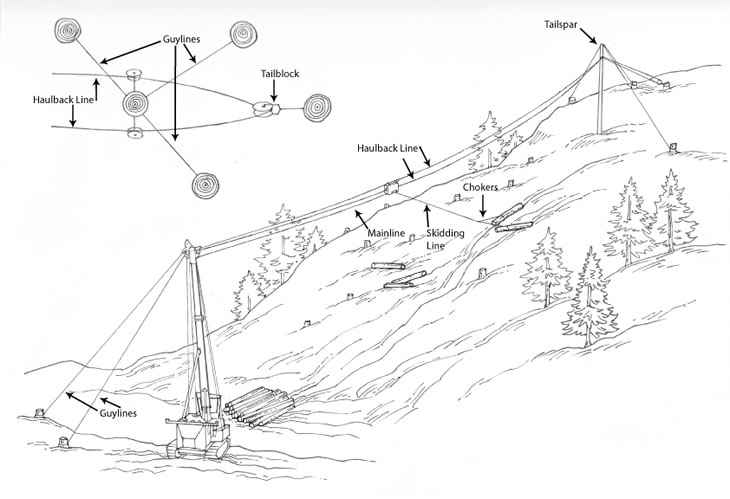
Figure 2. - Running Skyline Configuration.
Live Skyline
A live skyline is a system in which the skyline itself is raised and lowered to position the carriage. This is similar to the running skyline except the skyline is not also used as the haulback and the carriage is supported by only one cable. This system is operated with non-slackpulling carriages. This system only requires a two-drum yarder when operating uphill. A third drum for a haulback is required for downhill yarding and slopes less than 20%.
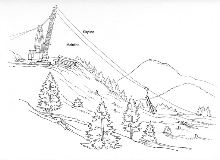
Figure 3. - Live Skyline Configuration.
Highlead
A highlead system is not a skyline and consists of a mainline and a haulback cable. It requires a minimum of two drums on the yarder. The only carriage a highlead system is capable of operating with is a grapple, otherwise it usually is configured with a butt rigging and chokers. It is a ground lead system except that lift is provided to the turn of logs by the height of the tower as the logs approach the landing. This system is limited to operating in clearcuts due to the nature of its setup. It may be operated in either an uphill or downhill yarding configuration.

Figure 4. - Haulback System.
Jammer or Tong Thrower
This is not a skyline system and consists of only one line, a mainline. The line either is pulled into the stand manually or is thrown by the yarder. It can operate with either chokers or a grapple. Yarding distances are usually limited to 300 feet or less. The prescription is either a clearcut or a heavy thinning. This is a ground lead system.
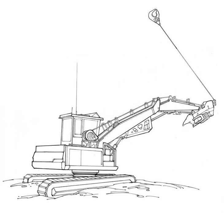
Figure 5. - Tong Thrower.
Mechanical Configurations
Cable yarding consists of many components that affect the planning and design of an operation. The basic components are the yarder and the carriage. The type of yarder and carriage available will determine the type of cable system that can be used.
Yarders
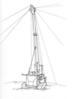
Figure 6. - Tower (Fixed Boom) Yarder.
Figure 7. - Swing Boom Yarder.
A rudimentary appreciation of yarder operation is of assistance in understanding the problems a yarding engineer has in running a yarder to operate the various cable yarding systems. This is of special concern when a skyline payload is marginal. There may be a difference between theoretical maximum payload and the actual maximum pay load as governed by yarder and logging system limitations. Some yarding systems are very demanding and require a very skilled yarding engineer to operate them effectively.
Yarders come with either a swinging boom or a fixed boom. Most swinging booms have a limited height of 30 feet to 60 feet. Fixed boom yarders can have towers as tall as 100 feet.
Swinging booms permit a wider skyline corridor and thereby reduce the number of yarder moves. This is a big advantage when grapple yarding.
A swing boom yarder will provide more deflection for uphill yarding than is available to a fixed tower of the same height if the fixed tower has to set a log length back of the fill slope. On the other hand, fixed towers are usually taller than the booms on swing boom yarders.
The carrier is the chassis of the yarder. Its function is to support the yarder equipment and allow transportation. The carrier can be categorized in four ways:
- What it moves on:
- Tracked
- Wheeled
- Skid - this type either is mounted on skids, or has a flat bottom, that allows the yarder to slide along the ground. This type often moves through the woods by winching themselves through the stand. This is the modern equivalent of the donkey engine.
- How it moves:
- Self-propelled - this is called a mobile yarder.
- Towed - this is a yarder mounted on a trailer that is pulled by another vehicle.
- Carried - this is typical of a skid mounted yarder that must be placed on a trailer for transport over long distances.
- Mounting for power-train- some yarders are run from the power take off of a separate tractor, while others have their own power source mounted on the chassis.
- The ability to swing - a swing yarder is capable of rotating on its base allowing it to swing the load out of the way on the landing or to place the load onto a log deck.
Figure 8. - Swing Machine Based Swing Yarder.
Figure 9. - Skidder Mounted Yarder.
Tower
The functions of the tower are to keep the cable off the ground and provide lift to the stems, especially near the landing. Towers can be categorized by the following
- Tower Mounting
- Integrated - This is the typical tower mounted directly to the chassis of the yarder.
- Independent - Independent spars are typically trees that had been topped and rigged. These are most often used as tailspars or intermediate spars.
- Size
- Small (<30ft)
- Medium (~60ft)
- Large (>90ft)
- Tower Structure
- Wooden spar
- Steel (tubular) tower - this is by far the most common.
- Lattice tower -Lattice towers are lighter but can be more easily damaged.
- Tower Assembly
- One-piece
- Folding
- Telescoping - for on-road transportation, larger towers are either folding or telescoping.
Towers are designed for a given cable size which should not be exceeded.
Smaller cables can be used but they aren't as well supported in the fairlead sheave grooves and will experience wear.
Truck road alignment may limit movement of large yarder-towers because of yarder length and tower overhang.
Guyline drums are considered part of the tower and the guylines and raising or hoisting lines are generally provided with the tower.
Undercarriages
Undercarriages for steel towers are designed for efficiency in yarding but they also have to be designed to meet highway load limits and to traverse steep, narrow, winding logging roads. The larger the yarder and tower the more complicated the design. Some of the largest machines have to be equipped with jeeps and pups, or must be disassembled to meet highway load limits and to traverse winding roads. A loader or crane is needed to disassemble a large yarder tower.
Trailer Mounted Undercarriage (TRLM)
These undercarriages are relatively inexpensive but require a log truck or highway tractor to move them any distance. They can be moved short distances by a crawler tractor if they are properly equipped.
Self Propelled Crawler Mounted Undercarriage (SPCM)
These machines are a little less expensive than SPRM but more than TRLM undercarriages. However, a lowboy is needed to make long moves. They are designed to facilitate short moves.
Self Propelled Rubber Mounted Undercarriage (SPRM)
These undercarriages speed up moves to new landings, units or sales. They eliminate the need for a log truck or highway tractor to make the move. However, they cost more than TRLM or SPCM undercarriages.
On long highway moves SPRM yarders can be pulled by a highway tractor to speed up the move.
Grade ability in the SPRM carriers is normally considered to be 25 percent and the minimum turning radius is approximately 50 feet. They have been moved on slopes up to 35 percent on occasion. A smooth grade with very little side slope is needed when moving a SPRM yarder tower off regular truck roads
Winches/Drums
The function of the winch sets on a yarder is to transfers the power from the power-train to the cables to do the work. A yarder can have 1 - 12 working winches. The more winches on the yarder the more versatile it is. The drum on the winch set stores the cable. While older yarders typically used mechanical drives to power the winches, modern yarders are all hydraulic for smoother and more continuous transfer of power. In many instances a cable needs to be held, or if gravity is pulling a cable off the drum then it needs to be slowed, hence the need for good brakes. When slowing a drum, the brake must dissipate a large amount of energy as heat. The older brakes were typically air cooled, but most modern yarders have water cooled brakes.
Interlocked drums are drums which act together to maintain the tension between two or more lines. They are used in running skylines to maintain the tension when moving the carriage.
Cab/Controls
The function of the cab and controls is to safely ‘house’ the operator and control the operation of the yarder. For older and/or smaller yarders, the operator may be standing next to the yarder during operation. On modern mobile yarders the cab is mounted high on the chassis to provide the best possible visibility for the operator.
Cable/Wire Rope
The cable used will determine the load capacity of the system and the maintenance schedule. Cable, or wire rope, is made up of wires that are wound into strands. The strands are then wound into the finished wire rope. There are many different configurations of wire rope. The direction in which the wires are wound into strands, the number of wires in each strand, the direction the strands are wound, the number of strands in the rope, and the material the rope is made of classify wire rope.
- A wire is a single metallic wire that is either round or shaped.
- A strand is a group of wires helically laid around a center in one or more layers.
- The core is an axial member around which strands are laid to form a wire rope. It may be either steel, natural fibers, polypropylene, or even a small-diameter wire rope.
- A rope is a group of strands helically laid around a core.
The number of strands and the number of wires per strand classify wire rope. For example, a 6x19 IWRC rope that has six strands, each of which is made up of 19 wires. It also has an independent wire rope core, IWRC. The number of wires per strand directly affects the flexibility and resistance to abrasion, the more wires per strand the more flexible and the higher abrasion resistance.
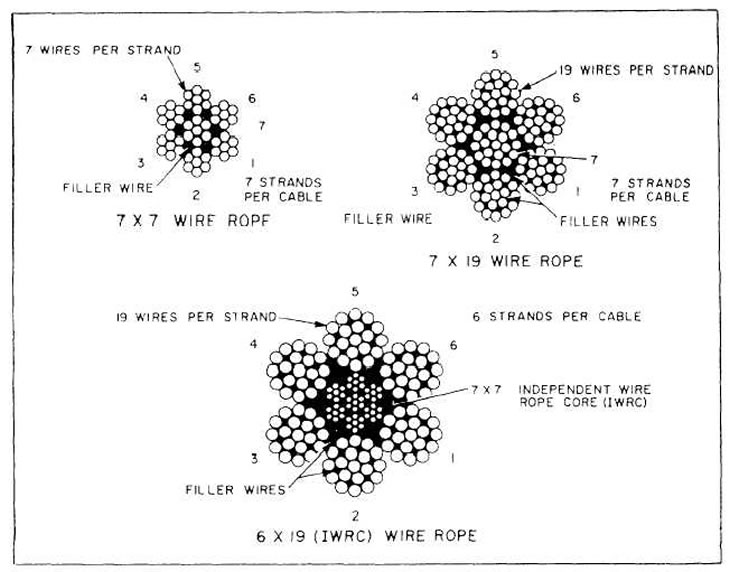
Figure 10. - Cross Sections of Wire Rope, Courtesy of Integrated Publishing.
The direction in which the strands are laid is the lay. A regular lay aligns the wires along the length of the rope for improved abrasion resistance. A lang lay aligns the wires at an angle to the length of the rope.
Much of the wire rope used today is swaged. Swaging compresses the wire rope axially which improves the life of the rope and increases the load capacity. The advantages of swaged rope are:
- increased strength
- increased drum capacity
- improved resilience to crushing and abrasion
- improved resistance to rotation on sheaves
- smoother surface improves spooling on drums with less vibration
Manufacturers provide tables with breaking strengths for their ropes. The safe working load, SWL, is a fraction of the breaking strength, usually one third. This is referred to as having a factor of safety of 3. As an example, a wire rope with a breaking strength of 103400 lbs has a SWL of 34500 lbs when the factor of safety is 3.
Damage to wire ropes can occur from:
- rubbing over rocks
- rubbing against each other
- crushing on the drum
- rubbing at the top of the tower
- overloading
- lack of lubrication
It is important to have good ropes and maintain those ropes to provide for the safety of the crew and prevent damage to equipment.
Carriage
A skyline carriage is a wheeled device that rides back and forth on the skyline for yarding. Carriages are described as either slackpulling or non slackpulling. Slackpulling refers to the ability to pull slack in the skidding line or have the skidding line pulled through the carriage, by hand or mechanically. A non-slackpulling carriage has no means of allowing the skidding line to be contained in or pass through it. Without special rigging, this prevents lateral yarding. A slackpulling carriage either permits the mainline to be used as a skid line and pulled through the carriage, or it has its own drum with a skid line that can be pulled out of the carriage to permit lateral yarding.
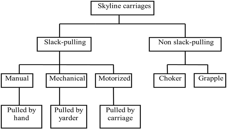
Figure 11. - Chart to Characterize Carriages.
Non-Slackpulling
This type of carriage has no means of allowing a skidding line to be contained in or pass through it. It may be moved laterally with a Dutchman line or by sideblocking. The chokers usually are shackled directly to the carriage or to a short line attached to the carriage.
Non-slackpulling carriages, because of their inability to laterally yard without damaging leave trees, should only be used on clearcuts. Attempts to use these carriages in partial cuts in the past have had dismal results.
Fall block systems do yard laterally, however, the carriage isn't held in position on the skyline. As a result, fall block systems may damage leave trees in a partial cut when the turn is laterally yarded to the skyline.
Grapple Carriage
A unique option for a carriage type is the grapple - shown in the chart as being a non-slack-pulling carriage. Using a grapple carriage eliminates the need for a choker setter and can save a lot of time. However there are quite a few limitations associated with the grapple - you can only pick up trees/logs directly under the skyline, and in most cases you are limited to picking up one tree/log at a time.
The design of a grapple carriage is similar to some of the mechanical slackpulling carriages in that they must provide a means to open or close the grapple. This can be done with a line from the yarder or by using an engine or power device in the carriage. The grapple carriage cannot yard laterally unless it is sideblocked.
Slackpulling
This type of carriage can have a self-contained skidding line or a mechanism to permit the skidding line to be pulled through it by hand or mechanically. The carriage may be further classified as to how the slack is actually pulled.
Slackpulled by Hand
This type of carriage uses a two drum yarder. The mainline passes through the carriage and becomes the skidding line. The carriage, after it is clamped to the skyline, acts as a block through which the mainline is pulled by the choker setter. A slack kicker may be used on the yarder to assist the choker setter in pulling slack.
This type of carriage is generally limited to uphill yarding (using a gravity outhaul) so that the choker setter can pull slack downhill with the assistance of gravity.
Slackpulled by Yarder
This type of carriage is designed so that a slackpulling line from the yarder pulls the skidding line out of the carriage. The skiddingline may be contained on a drum in the carriage, or it may be attached to the mainline from the yarder. The carriage may have a radio controlled clamp or be held in position by the haulback.
Slackpulled by Carriage
This type of carriage uses some type of power device in the carriage for pulling slack. The power may be in the form of mechanical springs, hydraulic motors, or diesel or propane-fueled engines. The carriage will clamp to the skyline and is remotely controlled by radio or by mechanical springs.
If mechanical springs or a propane engine is used, yarding is limited to level or uphill, due to the difficulty in pulling the mainline uphill.
Line Nomenclature
There are many names for the lines used in the different cable configurations. The basic terms are mainline, skyline, haulback, slackpulling, and dropline or skidding line. The skyline is the cable on which the carriage rides. All skyline systems contain a skyline. The mainline is the line that runs from the tower to the carriage. This cable pulls the carriage back to the landing. The haulback is used in downhill operations and where the line slope is less than 20% and the carriage requires assistance to get into the unit. A slackpulling line is used with mechanical slackpulling carriages that require a separate line to raise and lower the dropline. The dropline, or skidding line, is the line to which the grapple or chokers are attached. It may be attached to the mainline, as in a mechanical slackpulling carriage, or it may be mounted on a drum in the carriage.
The haywire or strawline is used when rigging a cable road, which is a small, light cable that can be more easily pulled into the unit. It is then attached to the larger operating lines to pull them into position.
Guylines are used to support the tower and any tail trees, tail spars, or intermediate supports. Yarders are equipped with drums holding the guylines necessary to support the tower.
The number of lines used in the system will dictate the number of drums required on the yarder. The most basic setup requires just a mainline and one drum on the yarder. The most drums used are four and will contain a skyline, mainline, haulback, and slackpulling line.
Cable Operation Crew
There are many crew positions in cable yarding operations. Typical titles and descriptions are included here.
- Side Rod - the supervisor of the logging operation.
- Hooktender - the person responsible for cable road changes and helps with supervision.
- Rigging Slinger - The person that supervises the choker setting operation, selecting logs to be choked and sending radio signals to the yarder operator.
- Choker Setters - Attaches the choker cables to the logs.
- Chaser - Unhooks the choker cables from the logs at the landing.
- Yarder operator - runs the yarder.
- Loader Operator - runs the loader.
Operational Considerations
Physical Limitations
Cable yarding systems are typically used where steep slopes do not allow ground based extraction equipment to operate safely or where ground conditions do not permit travel by ground based extraction equipment.
Deflection
Skyline configurations require adequate deflection in order to carry a load. Deflection refers to the amount of sag in the skyline. Tension is required to suspend the skyline over its length. The more tension required to achieve suspension over obstacles, the lower the payload that can be carried by the line. Higher tensions also require stronger anchors. Deflection is affected by the lay of the ground under the skyline and slope over which the skyline is run. A convex slope will limit the amount of deflection that can be achieved and will often require intermediate supports.
Anchors
Cable operations, other than tong throwers, are limited by the availability of suitable anchors. Anchors are necessary to support the yarder, intermediate supports, and tailholds. Standing trees or stumps are often used as anchors. Suitable trees are determined by tree size, soil holding capacity, and their locations in respect to the equipment being anchored. Where suitable stump or tree anchors are not present, deadman anchors or equipment may be used. Deadman anchors are logs buried in the ground to provide an anchor. Equipment, such as a heavy crawler tractor, may be used as a mobile anchor where available and necessary.
Treatment Options
Highlead cable operations are used in clearcut treatments due to the rigging requirements. Skyline configurations can be used in either clearcutting or thinning operations. Corridors, normally 8 to 12 feet wide, must be cut in the stand to allow free passage of the logs. In visually sensitive areas, parallel corridors should be used. Radial parallels result in clearcut areas where the corridors converge at the landing.
Safety Concerns
There are a number of safety issues when working around cable operations. Anchor failure can be mitigated using solid anchors and proper anchor building techniques. Cable failures can result from inadequate deflection, poorly maintained cables, trying to haul loads larger than the safe working load of the cables, and numerous other factors.
Workers should never work in the bight of the line. Systems must be designed and laid out to avoid this possibility.
Downhill yarding landings should be designed with adequate runout space to prevent logs and debris from rolling downhill into the landing area where people and equipment are working.
System Interactions
Manual felling is often used with cable extraction due to the inability to operate mechanical equipment in the stand. In some cases, mechanical felling and processing may be used where soil conditions and terrain permit. Mechanized felling equipment may not have the same restrictions as extraction equipment since ground disturbance can be minimized using slash mats and fewer passes over the same ground. Mechanized equipment has the advantage of locating turns of logs in one place, decreasing the amount of time required to choke a turn. Mechanized felling does increase the number of corridors required to yard the stand.
Research
The following is a selection of representative research studies and reports done on harvest systems that include cable extraction. These reports may be used to get an idea of productivity and impacts of different systems and uses of cable extraction as well as some of their limitations. When reading these reports, keep in mind that they describe specific systems and stand treatments. Trying to apply the lessons learned from these reports to systems and treatments outside of the studies’ scope may have unintended or unforeseen consequences.
This is not a complete listing of research on the use of cable systems. Additional information can be found at the USDA Forest Service Treesearch website. This site provides reports on research performed by Forest Service Research and Development scientists and their collaborators.
- Title: Yarding cost for the Koller K300 cable yarder: results from field trials and simulations
Authors: Huyler, Neil K.; LeDoux, Chris B.
Date: 1997
Source: The Northern Journal of Applied Forestry. 14(1): 5-9.
Station ID: JRNL-NRS-14
Description: This paper describes results from field studies and simulation that can be used to estimate the yarding cost for the Koller K300 cable yarder. Yarding costs can be estimated for clearcuts and light and heavy thinnings in eastern hardwoods. Yarding costs can be estimated with a handheld calculator, or the data can be incorporated into stump-to-mill desktop PC and mainframe computer programs. The results can be a valuable tool for loggers, managers, and planners considering the use of small- to medium-size cable yarders to extract timber from eastern hardwood stands. - Title: Environmentally Sound Timber Extracting Techniques for Small Tree Harvesting
Author: Wang, Lihai
Date: 1999
Source: 199 ASAE Annual International Meeting, Paper No. 995053, Toronto, Ontario, Canada, July 18-21, 1999
Description: Due to large area disturbed and great deal of energy cost during-its operations, introducing or applying the appropriate timber extracting techniques could significantly reduce the impact of timber extraction operations to forest environment while pursuing the reasonable operation costs. Four environmentally sound timber extraction techniques for small tree harvesting, particularly for thinning operations, were presented and introduced in this paper. These techniques included animal skidding and animal-machine, single circulating cable yarding system, small farming tractor, and mini forwarder. The results of evaluation, test or practices indicated that these timber extracting techniques are feasible, applicable and reasonable in small tree harvesting with a relatively low impact to environment and a moderate operation cost.
- Title: Economics of hardwood silviculture using skyline and conventional logging
Authors: Baumgras, John E.; Miller, Gary W.; LeDoux, Chris B.
Date: 1995
Source: In: Lowery, G.; Meyer, D., eds. Proceedings of the 23rd annual hardwood symposium, advances in hardwood utilization: following profitability from the woods through rough dimension; 1995 May 17-20; Cashiers, NC. Memphis, TN: National Hardwood Lumber Association: 5-17.
Description: Managing Appalachian hardwood forests to satisfy the growing and diverse demands on this resource will require alternatives to traditional silvicultural methods and harvesting systems. Determining the relative economic efficiency of these alternative methods and systems with respect to harvest cash flows is essential. The effects of silvicultural methods and roundwood prices on harvesting revenue are presented for skyline and conventional skidder logging. Silvicultural methods evaluated include single-tree selection, group selection, even-age management, two-age management, diameter-limit cutting, and commercial thinning. Results indicate that harvesting systems had less impact on harvesting revenue than silvicultural methods or roundwood prices, and that hardwood markets can significantly affect economic trade-offs associated with forest management alternatives.