| Background
Firefighters now have a way to remotely activate pumps to charge sprinkler
systems for structure protection. Historically, when a wildfire threatens
structures, firefighting crews would prepare the structures with pumps
and sprinkler systems. Once the threat was imminent, firefighters—at
great risk—rushed to the structures to start the pumps often with
ember showers raining down upon them.
The San Dimas Technology and
Development Center (SDTDC) has developed the technology to remotely activate
a pump for structure protection, avoiding this risk to firefighters. This
system would work well to protect improvements in remote wilderness areas.
The
Pump and Engine
SDTDC purchased a BB-4 pump because of its capability to adapt to a remote
electronic starting system (figure 1). The pump produces up to 425 psi
(or 110 gallons per minute), which is more than enough to operate long
hose lays with significant elevation changes. The BB-4 pump end is a horizontal
4-stage centrifugal pump. An opposed twin cylinder, 18 horsepower, Briggs
and Stratton engine with electric and recoil starting systems powers the
BB-4. The complete pump system weighs 143 pounds and uses approximately
1.8 gallons of fuel per hour during pumping operations. When the remote
start system is not connected, the BB-4 can be used for conventional operations.
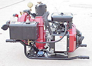 |
| Figure
1—BB-4 pump. |
The
Ground Receiver and Handheld Transmitter
The electronic ground receiver system (figure 2) is housed in a plastic
case. It is a commercial automotive remote starting system. Cables connect
the ground receiver to the electronic starter on the BB-4. The handheld
transmitter (figure 3) is compliant with Federal Communication Commission
regulations regarding communication interference. It is a low power FM
device similar to those used in automotive keyless entry and antitheft
systems. The display on the handheld transmitter was intended to indicate
when a car is running, but it can serve to indicate that the pump is running.
All electronic components are commercially available automotive-grade
hardware.
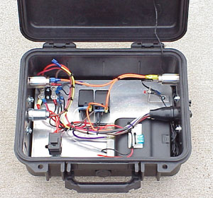 |
| Figure
2—Electronic ground receiver system. |
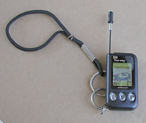 |
| Figure
3—Handheld transmiter. |
The
Battery Pack
The battery pack (figure 4) is a 12-volt, power booster capable of providing
400 amp-hours. The stock alligator clips were removed and replaced with
a commercial disconnect plug. This facilitates connection while making
it impossible to cross polarity and damage the electronics or starter.
A 12-volt car battery could be used if caution were taken to ensure proper
polarity before connecting.
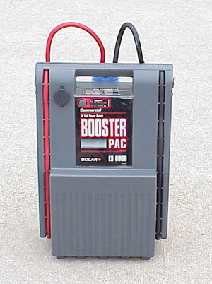 |
| Figure
4 —Battery pack |
The
Lights
Once the pump develops pressure, lights (figure 5) flash to indicate that
the pump is operating. SDTDC is currently testing several lighting systems
and colors to determine which types of lights and colors are better seen
through smoke. The Center is also investigating strobe light technology
to improve pump visibility. Figure 6 shows the pump, as it would look
during normal operating conditions.
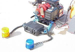 |
| Figure
5—Lights flash to indicate pump is operating. |
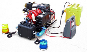 |
| Figure
6—The pump during normal operating conditions. |
The Test
On March 14, 2001 the remote pump system was tested at SDTDC using a helicopter
from the Angeles National Forest (figure 7). Following a detailed test
plan, the pump was tested at the maximum test height of 2,000 ft. The
test plan called for three successful pump starts at this altitude. The
pump was successfully started at each attempt. It was a critical part
of the test to see how the remote handheld transmitter worked among the
electronic systems of a firefighting helicopter. No interference with
the helicopter electronic systems, including the air to ground radio systems,
were identified. The technician in the helicopter keyed the remote handheld
transmitter from inside the ship and did not have to lean out or position
himself in any special way to activate the pump below. It is also important
to note that the remote pump can be activated from a ground position as
long as the line of sight is clear of obstacles.
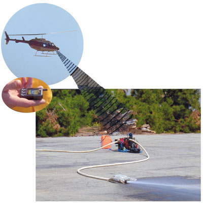 |
| Figure
7—Testing remote pump system from a helicopter. |
Field
Evalutation
Field evaluation is a critical step of the testing process. The pump and a structure protection kit will be
located at SDTDC. Our goal for the next fire season is to test the pump during wildland fire conditions where
structures are threatened.
Information
All of the hardware to build this remote starting pump is commercially
available. Contact the SDTDC fire program leader at 909-599-1267 x234
for specifications, cost, plans, diagrams, or other information.
|